Or Gate Internal Circuit Diagram
And gate circuit diagram & working explanation Gate logic Gate circuit diagram circuits led working full integrated circuitdigest
Scavenger's Blog: OR Gate
Gate transistor using circuit diagram schematic simple resistor sharing two designing emitter circuits simplest paralleled followers common Circuit adder electrical4u logical principle Or gate schematic diagram / logic gates and gate or gate truth table
Logical or gate
(a) what are logic gates?(b) draw a circuit diagram for dual-input andDesigning or gate circuit using transistor And gate: what is it? (working principle & circuit diagram)What is or gate?.
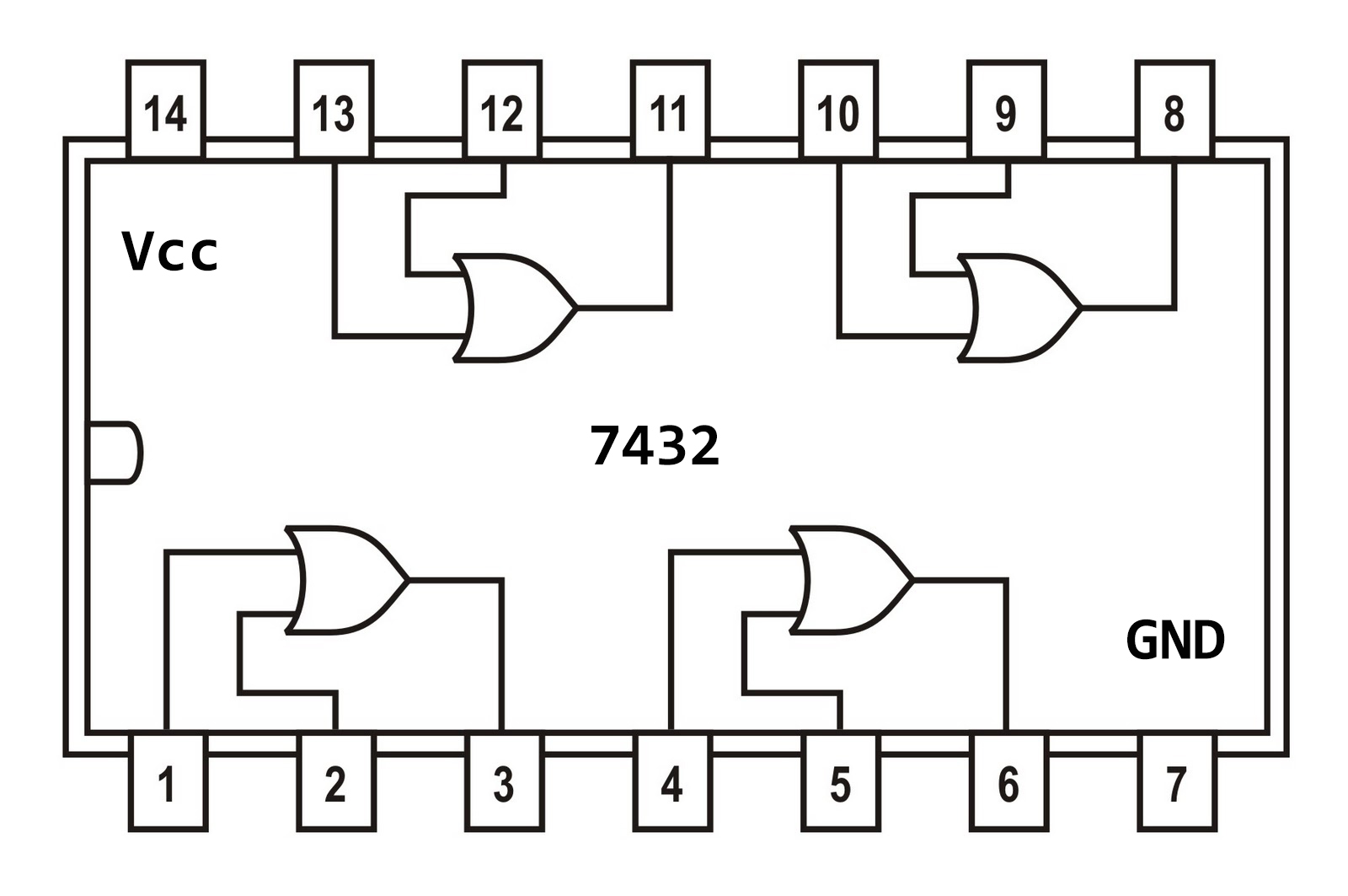
Gate logic diodes where resistanceScavenger's blog: or gate 7432 circuit integrated logic input gates ttl 74ls32 scavengerCdot represented.

The diagram of the logic gate circuit is given below. the output y of
.
.


The diagram of the logic gate circuit is given below. The output Y of

(a) what are logic gates?(b) Draw a circuit diagram for dual-input AND

Designing OR Gate Circuit using Transistor
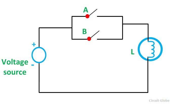
What is OR Gate? - Logic Symbol & Truth Table - Circuit Globe

AND Gate Circuit Diagram & Working Explanation
Scavenger's Blog: OR Gate

Or Gate Schematic Diagram / Logic Gates And Gate Or Gate Truth Table